BK MIKRO 7 is a broken tool detection system designed for tool as well as for object and free space monitoring applications. It combines the features of the BK Mikro 4 and BK Mikro 5 into a smaller, faster package ideal for Swiss style machines or anywhere that space is at a premium. The controller is common for either the BK7SC or BK7RLSC scanners.
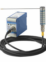
THE COMPLETE BK MIKRO 7 SYSTEM INCLUDES:
-
Control unit - BK7CTRL
-
Sensor (scanner) - TK7A or TK7RL
-
Connection cable - BK7C5
-
Mounting Bracket - BK7-8MB
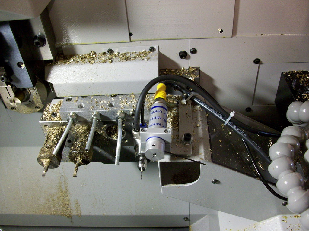
BK Mikro 7 typical uses:
Monitoring of a scanning position or tool whose precise location has been previously entered by "teach-in" or "learn". This position is then checked after each cycle to verify the tool or position is still present with in either a +/- 3 or 10 degree window.
-
Monitoring a scanning range or position selectable via two adjusting switches. This is used to carry out tool checks on tools whose diameter varies more than the +/- 10 degree checking window set with a Teach/Learn cycle.
-
Monitoring an area for free space using the two adjustable switches to set the scanning range.
-
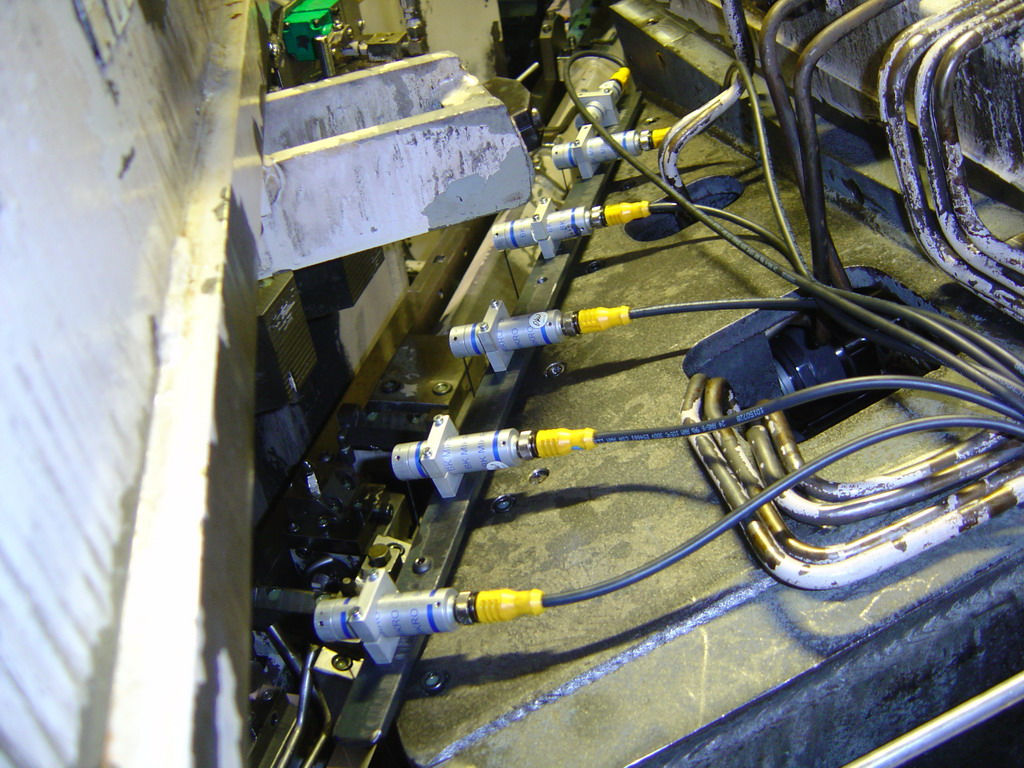
A typical free space monitoring application would be to verify a part has been ejected from the sub-spindle of a lathe before the main spindle tries to load another part into it.
Principle of Operation:
Once a position is set either with a Teach/Learn or via the adjusting switches the system is ready for operation. Simply apply a 24vdc signal to the "Start" terminal to initiate the scanning cycle (this can be done via the CNC, PLC or with a relay). The wand will rotate to the selected position and verify that the tool or object is present. If everything is alright the unit will output an "OK" signal to allow the machine cycle to continue. If the tool is broken the wand will travel past the stored position and the controller will output a "KO" signal to let the machine know there is a problem and shut down automatically. The wand must also travel to a minimum position. This is important because if the wand is blocked with chips or an obstacle the unit will output a fault alerting the operator that there is a problem.
Competitor systems only fault if the wand travels past the checking position completing an internal circuit (limit switch). This will allow a broken tool to go undetected because the wand is stuck and the unit thinks everything is ok allowing for scrap parts or machine crashes.
BK Mikro 7 using the BK7RLSC is a broken tool detection system designed to swing right then left to detect two tools. The BK7RL also has the capability to check only one of the two stored positions by applying voltage to the S1 or S2 terminal. This is useful if multiple parts are run down the same line and require different tooling for specific parts.
Principle of Operation:
For initial setup of the unit, place the wand between the two tools that you wish to monitor. Supply a 24vdc signal to the "Teach" terminal and the wand will move left until it touches the first tool then move right until it touches the second tool. The wand then centers itself between the two tools and this becomes its home position. You can also set the wand to the outside of the tools and it will rotate around and touch the outside of the tools. This is useful if having the wand's home position between the tools is not possible due to spindle or slide movement.
Once the positions are learned to check the tools simply apply a 24vdc signal to the "Start" terminal to initiate the scanning cycle (this can be done via the CNC, PLC or with a relay). The wand will rotate to the selected position and verify that the tools are present. If everything is alright the unit will output an "OK" signal to allow the machine cycle to continue. If either of the tools is broken the wand will travel past the stored position and the controller will output a "KO" signal to let the machine know there is a problem and shut down automatically. Each position is checked within a +/- 3 degree or 10 degree window depending on controller setting.
Further features enabling customized system configuration include:
-
Fault and OK outputs are Relay Contacts which can be selected to either normally open or normally closed.
-
Selection of clockwise or counter-clockwise travel direction for the scanning wand.
-
Two settings of controlled acceleration and deceleration allowing for the checking of small diameter tooling. (down to 0.005 depending on tool that is being checked)
-
Internal diagnostics which detect cable breaks.
-
Two checking windows when using the "Learn" feature either +/- 3 or 10 degrees.
-
Scanning in one direction or in both directions depending on scanner
-
Automatic detection of home position (point of reference between scanning positions BK7RLSC)
Control Unit:
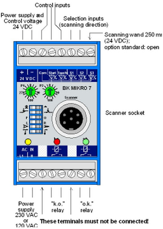
Controller Technical Data:
-
Housing: Insulated Material Housing, Protection Class
-
Protection Type: IP 20
-
Dimensions (W x H x D): 45mm x 75mm x 107.5mm
-
Case Mountings: DIN Rail, 35mm, to DIN EN 50022
-
Power Supply Voltage: 24 VDC or 120 VAC
-
Power Consumption: 6 VA max
-
Control Voltage: 24 VDC (internal/external)
-
Inputs: Input Current: 5mA approx.
-
Pulse Duration: 6ms min.
Scanner:
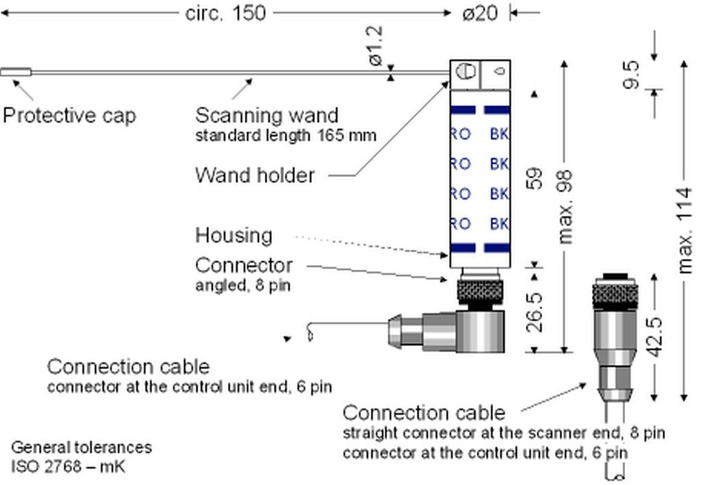
Scanner Technical Data:
-
Housing: Anodized Aluminum
-
Protection Type: IP 67
-
Wand Length: 165mm (standard)
-
Scanning Angle: 0° to 270°
-
Control Unit Connection: Connector, M12x1, 3 pins
-
Temperature Range: 0°C to +80°C
-
Sensing Cycles: > 10 million with normal deceleration