technatool
BK MIKRO 8

BK MIKRO 8

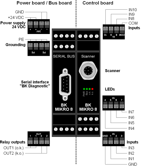
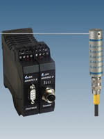
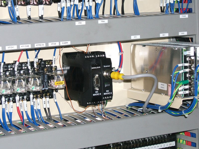
BK MIKRO 8 is a broken tool detection system designed mainly for broken tool detection inside the tool changer of machining centers adding little or no additional cycle time. The controller stores up to 128 different tool lengths in memory and is controlled using M-Code combinations or a custom Macro. The system can check tools whose lengths vary as much as 15 inches from the shortest to longest in the changer. Each of the 128 different tools can have individual tolerance ranges set roughly between 1mm-25mm. There is also a BK Mikro 8 system available which is configured using Profibus instead of digital I/O.
BK Mikro 8
(Click here to view the video of scanner working inside tool changer)

The complete BK MIKRO 8 system includes:

  • Control unit
  • Scanner (motor) - TK8A
  • Connection cable - BKC10
  • Mounting Bracket - BK7-8MB

The BK Mikro 8, like all of the other BK Mikro systems, can also be used to check for free space as well as part presence applications.

Principle of Operation:

First all of the tools lengths need to be taught and stored in the BK Mikro 8 control's memory using a Macro or binary M-code combination which is outputted from the machine's CNC control. These lengths are calculated using the angle away from the home position that the wand travels to before contacting the tip of the tool. Once all of the tool lengths are stored into memory the system will know what angle to check when a specific tool is called up. After the tool is finished machining and put back into the tool changer the BK Mikro 8 will check the length and compare it to the stored data. If the length is within the tolerance window that is set for that tool the unit will output an "OK" signal to allow the machine cycle to continue. If the tool is broken the wand will travel past the stored position and the controller will output a "KO" signal to let the machine know there is a problem and shut down automatically.
BK Mikro 8 Operating Principle
BK Mikro 8 Configuration
  • Fault and OK outputs are Relay Contacts which can be selected to either normally open or normally closed and can be set to momentary or latching.
  • Selection of clockwise or counter-clockwise travel direction for the scanning wand.
  • Four settings of controlled acceleration and deceleration allowing for the checking of small diameter tooling
  • Internal diagnostics which detects cable breaks.
  • Tolerance adjustments roughly between 1mm-25mm
  • Software to backup settings and save them to disk

Control Unit:

BK Mikro 8 Control Unit

Controller Technical Data:

  • Housing: Insulated Material Housing, Protection Class
  • Protection Type: IP 20
  • Dimensions (W x H x D): 45mm x 99mm x 114.5mm
  • Case Mountings: DIN Rail, 35mm, to DIN EN 50022
  • Power Supply Voltage: 24 VDC +/- 20%
  • Power Consumption: 10 VA max
  • Control Voltage: 24 VDC +/- 20%
  • Inputs: Input Current: 5mA approx.

Scanner:  BK Mikro 8 Scanner Technical Data

Scanner Technical Data:

  • Housing: Anodized Aluminum<
  • Protection Type: IP 67
  • Wand Length: 380 mm, with scanning plate 80 mm x 15 mm (standard)
  • Scanning Angle: 0° to 300°
  • Control Unit Connection: Connector, M12x1, 8 pins
  • Temperature Range: 0°C to +80°C
  • Sensing Cycles: > 10 million with normal deceleration

Request For Consultation

footer_q_hr

CapImage