The two scanner variations of the type TK7 have identical features. The only difference is that in variation “A” the rotational movement is limited by a mechanical stop inside the housing while the scanner “RL” can rotate in both directions without stopping. This is for checking two tools. These scanners are best suited for tight spaces where a larger scanner may not fit, such as Swiss style machines or multi-spindle heads.
The Complete BK MIKRO TK7A/RL System Includes
-
Control unit
-
I/O Unit- BKM9I/O (optional)
-
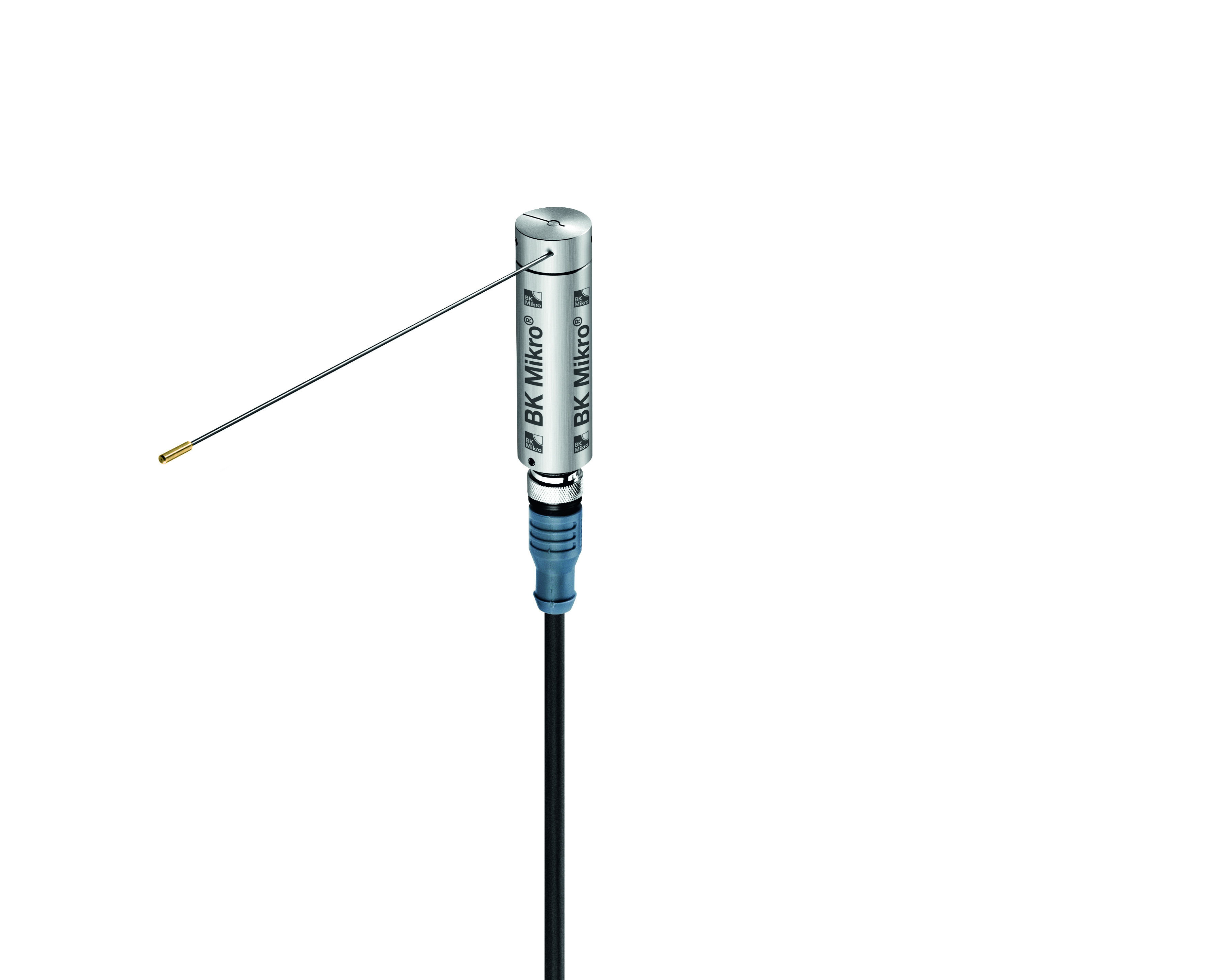
Scanner (motor) - TK7A or TK7RL
-
Connection cable
-
Mounting Bracket - BK7-8MB
TK7A/RL Typical Uses:
-
Monitoring of a scanning position or tool whose precise location has been previously entered by "teach-in" or “learn”. This position is then checked after each cycle to verify the tool or position is still present within a +/- 1.2°-25° user defined window.
-
Monitoring both right and left directions to check 2 tool positions (TK7RL)
-
Monitoring a scanning range or position selectable via two adjustable switches (when combined with the BKM9I/O).
-
Monitoring an area for free space using the software or the two adjustable switches on the BKM9I/O to set a window.
-
A typical free space monitoring application would be to verify a part has been ejected from the sub-spindle of a lathe before the main spindle tries to load another part into it.
Principle of Operation TK7A:
Once a position is set either with a Teach/Learn or via the adjusting switches the system is ready for operation. Simply apply a 24vdc signal to the "Start" terminal to initiate the scanning cycle (this can be done via the CNC, PLC or with a relay). The wand will rotate to the selected position and verify that the tool or object is present. If everything is alright the unit will output an "OK" signal to allow the machine cycle to continue. If the tool is broken the wand will travel past the stored position and the controller will output a "KO" signal to let the machine know there is a problem and shut down automatically. The wand must also travel to a minimum position. This is important because if the wand is blocked with chips or an obstacle the unit will output a fault alerting the operator that there is a problem.
Principle of Operation TK7RL (Checking 2 Tools):
For the initial setup of the unit, place the wand between the two tools that you wish to monitor. Supply a 24vdc signal to the "Teach" terminal and the wand will move left until it touches the first tool then move right until it touches the second tool. The wand then centers itself between the two tools and this becomes its home position. You can also set the wand to the outside of the tools and it will rotate around and touch the outside of the tools. This is useful if having the wand's home position between the tools is not possible due to spindle or slide movement.
Once the positions are learned, to check the tools simply apply a 24vdc signal to the "Start" terminal to initiate the scanning cycle (this can be done via the CNC, PLC or with a relay). The wand will rotate to the selected position and verify that the tools are present. If everything is alright the unit will output an "OK" signal to allow the machine cycle to continue. If either of the tools is broken the wand will travel past the stored position and the controller will output a "KO" signal to let the machine know there is a problem and shut down automatically. Each position is checked within the degree tolerance programmed into the controller.
Scanner
.jpg)
Scanner Technical Data:
-
Housing: Anodized Aluminum
-
Protection Type: IP 68
-
Wand Length: 165 mm (standard)
-
Scanning Angle: TK7A max. 270°, TK7RL max. 360°
-
Control Unit Connection: Connector, M12x1, 8 pins
-
Temperature Range: 0°C to +80°C
-
Sensing Cycles: > 10 million with normal deceleration